Home / Blog / Detecting Broken Rotor Bars With The Ric Test
05-03-2026
Detecting broken rotor bars with the RIC test
Rotorstaaf defecten zijn verantwoordelijk voor een deel van alle motoruitval.
Het probleem: scheuren en poreuze plekken in de kooi zijn bij visuele inspectie onzichtbaar. De RIC-test maakt ze detecteerbaar. Spanningsloos, zonder demontage.
What is the Rotor Influence Check (RIC test)?
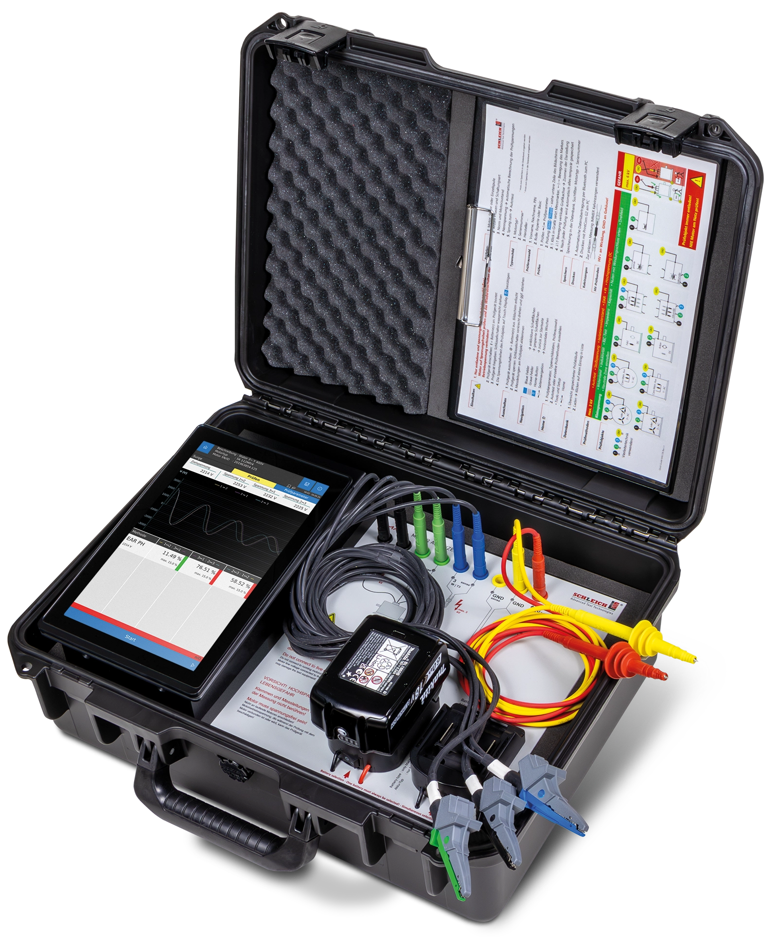
The Rotor Influence Check is a static inductance measurement on the assembled motor (rotor inside stator). The motor is de-energised but the shaft rotates freely. A low-voltage alternating current is applied to the stator winding. The MotorAnalyzer 3 uses a 50 Hz measurement signal for this purpose.
The inductance per phase is measured at each rotor position. The stator inductance is influenced by the residual magnetism in the rotor and the permeability variation caused by the individual rotor bars as they rotate beneath the stator winding. Hence the name: the rotor influences the measurement.
The rotor is manually rotated in fixed steps over 360°, using a degree disc on the shaft. At each position, the instrument measures the inductance of all phases. The result is a series of inductance values per phase per rotor position.
Measurement procedure with the MotorAnalyzer 3
Determining the step size from the rated speed
The step size per measurement is determined by the number of pole groups of the motor. Calculate this as follows:
| Speed (nameplate) | Sync. speed | Number of pole groups | Step size |
| ~2900 rpm | 3000 rpm | 2 | 10° |
| ~1450 rpm | 1500 rpm | 4 | 5° |
| ~960 rpm | 1000 rpm | 6 | 3.3° |
| ~720 rpm | 750 rpm | 8 | 2.5° |
Standard templates are available that IONIO can supply to maintain the exact step size (3, 5 and 10 degree steps). Send e-mail
- Motor de-energised and locked out (LOTO)
- Shaft free to rotate, coupling disconnected if necessary
- Degree disc mounted on the shaft for accurate positioning
- MotorAnalyzer 3 connected to the motor terminals (method phase 1↔phase 2 or according to instrument settings)
- Measure at each position, then rotate the rotor step by step until a full revolution (360 degrees) is completed
The MotorAnalyzer 3 calculates the percentage deviation of the measured inductance from a reference value (Δ_ref) at each measurement position. The default threshold is set at 10%.
Values within ±10%: motor approved (OK).
Values outside ±10%: deviation detected — instrument shows red NOK indication.

Practical example: defective rotor detected
The example below shows a RIC measurement on a motor with rotor bar defects present. The measurement was carried out in steps of 20°, method phase 1↔2.
| Position | Inductance (mH) | Δ_ref (%) | Assessment |
| 6: 100° | 108.881 mH | -0.09 % | OK |
| 7: 120° | 110.552 mH | 1.44 % | OK |
| 8: 140° | 111.794 mH | 2.58 % | OK |
| 9: 160° | 136.139 mH | 24.92 % | NOK — DEVIATION |
| 10: 180° | 108.037 mH | -0.87 % | OK |
| 11: 200° | 108.138 mH | -0.77 % | OK |
| 12: 220° | 110.280 mH | 1.19 % | OK |
Analysis: At position 9 (160°), the inductance jumps from a baseline of approximately 109 mH to 136 mH. That is a deviation of 24.92% — well above the 10% threshold. In the graph, two red peaks appear, repeating consistently per pole pitch. This pattern is characteristic of a broken or severely damaged rotor bar: the defect passes each pole group identically, causing the outlier to repeat periodically across the full revolution.
Limitations of the RIC test
The RIC test is a valuable part of a static motor testing protocol, but has specific limitations that affect interpretation.
Residual magnetism required
The measurement relies on residual magnetism in the rotor after operation. A brand-new motor that has never been energised, or a motor that has been idle for an extended period, may have insufficient residual magnetism. The result is a flat plot with no diagnostic value — even if the rotor is healthy.
Copper bar rotors produce little signal
Motors with copper bars (typically medium voltage, > 3 kV) have virtually no residual magnetism due to higher material quality and larger air gap dimensions. The RIC plot remains flat. This is normal for this motor type, but renders the test unsuitable as a condition monitoring method.
Large air gap dimensions attenuate the signal
Magnetic field strength decreases with the square of distance. Older motors (U-frame) and high-power motors with larger air gaps produce an attenuated rotor contribution to stator inductance. Beyond a certain air gap width, the signal can no longer be reliably interpreted.
No absolute reference values available
Motor manufacturers do not publish nominal inductance values. The RIC test is therefore only useful as a trend measurement or comparison against a reference motor of the same type. A one-off measurement of an unknown motor without historical data cannot be assessed conclusively.
Positional accuracy is critical
An error in step size — too large or too small a rotation increment — distorts the results. Manual indexing without a degree disc introduces measurement errors that are too large. The degree disc on the shaft is not an optional aid but a measurement requirement.
Early crack formation not always detectable
An initial hairline crack in a rotor bar does not always cause a measurable resistance change when the motor is stationary and cold. Only under thermal load does the crack open. The RIC test, performed on a cold motor, will miss the fault in that case. Motor Current Signature Analysis (MCSA) under load is more sensitive for this purpose.
Related blogs

Calibration
Electric motor testing
Your calibration certificates always at hand: the new IONIO Training Portal is live
View article
Electric motor testing
Function tester
Hot hipot during functional testing: maximum assurance that all circuits are active
View article
Also collaborate on technical challenges?
Then you have come to the right place at IONIO!

Gijsbert at IONIO is here to help you.
At IONIO, we not only supply advanced testing and measurement systems, but also offer clear and expert advice to optimise the testing of your product.
Find out how we can improve your business processes. A consultation can be scheduled in no time!